 Datasheet下载
- 型号: HAIS 100-TP
- 制造商: LEM
- 库位|库存: xxxx|xxxx
- 要求:
| 数量阶梯 | 香港交货 | 国内含税 |
| +xxxx | $xxxx | ¥xxxx |
查看当月历史价格
查看今年历史价格
HAIS 100-TP产品简介:
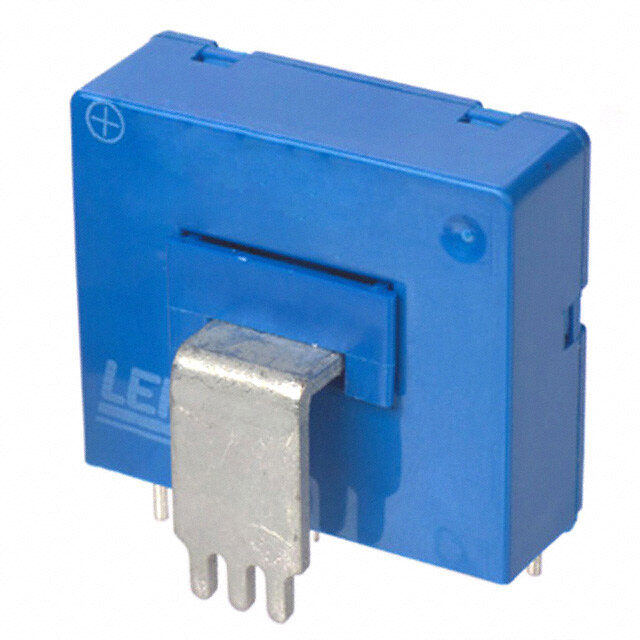
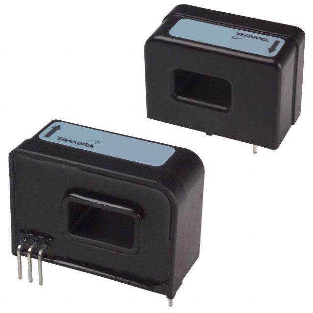
ICGOO电子元器件商城为您提供HAIS 100-TP由LEM设计生产,在icgoo商城现货销售,并且可以通过原厂、代理商等渠道进行代购。 HAIS 100-TP价格参考。LEMHAIS 100-TP封装/规格:电流变送器, 电流传感器 100A 1 通道 霍尔效应,开环 双向 模块。您可以下载HAIS 100-TP参考资料、Datasheet数据手册功能说明书,资料中有HAIS 100-TP 详细功能的应用电路图电压和使用方法及教程。
| 参数 | 数值 |
| 产品目录 | |
| 描述 | SENSOR CURRENT 100A 5V MOD |
| 产品分类 | |
| 品牌 | LEM USA Inc |
| 数据手册 | |
| 产品图片 |
|
| 产品型号 | HAIS 100-TP |
| rohs | 无铅 / 符合限制有害物质指令(RoHS)规范要求 |
| 产品系列 | HAIS |
| 产品目录绘图 |
|
| 产品目录页面 | |
| 传感器类型 | 霍尔效应, 开环 |
| 其它名称 | 398-1028 |
| 包装 | 托盘 |
| 响应时间 | 5µs |
| 安装类型 | 通孔 |
| 封装/外壳 | 模块 |
| 工作温度 | -40°C ~ 85°C |
| 极化 | 双向 |
| 标准包装 | 6 |
| 灵敏度 | - |
| 用于测量 | AC/DC |
| 电压-电源 | 5V |
| 电流-检测 | 100A |
| 电流-电源(最大值) | 19mA |
| 精度 | ±1% |
| 线性度 | ±0.5% |
| 输出 | 比率, 电压 |
| 通道数 | 1 |
| 频率 | DC ~ 50kHz |


- 商务部:美国ITC正式对集成电路等产品启动337调查
- 曝三星4nm工艺存在良率问题 高通将骁龙8 Gen1或转产台积电
- 太阳诱电将投资9.5亿元在常州建新厂生产MLCC 预计2023年完工
- 英特尔发布欧洲新工厂建设计划 深化IDM 2.0 战略
- 台积电先进制程称霸业界 有大客户加持明年业绩稳了
- 达到5530亿美元!SIA预计今年全球半导体销售额将创下新高
- 英特尔拟将自动驾驶子公司Mobileye上市 估值或超500亿美元
- 三星加码芯片和SET,合并消费电子和移动部门,撤换高东真等 CEO
- 三星电子宣布重大人事变动 还合并消费电子和移动部门
- 海关总署:前11个月进口集成电路产品价值2.52万亿元 增长14.8%


PDF Datasheet 数据手册内容提取
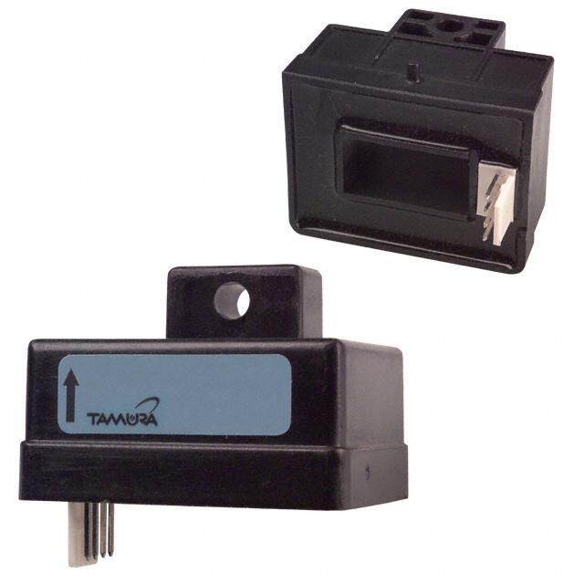
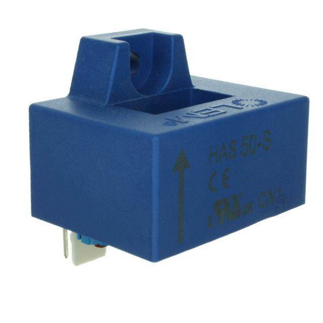
Current Transducer HAIS 50 .. 400-P I = 50 .. 400 A PN HAIS 50 .. 150-TP I = 50 .. 150 A PN For the electronic measurement of currents: DC, AC, pulsed..., with galvanic separation between the primary circuit and the secondary circuit. All data are given with R = 10 kΩ L Electrical data Primary nominal Primary current Type rms current I (A) measuring range I (A) PN PM Features 50 ±150 HAIS 50-P/50-TP 1) 100 ±300 HAIS 100-P/100-TP 1) ● Hall effect measuring principle 150 ±450 HAIS 150-P/150-TP 1) ● Galvanic separation between 200 ±600 HAIS 200-P primary and secondary circuit 400 ±600 HAIS 400-P ● Insulation test voltage 2500 V G Theorical sensitivity @ I 0.625 V/ I ● Low power consumption Th PN PN V Analog output voltage @ I V +(0.625·I / I ) V ● Single power supply +5 V out P OE P PN V Reference voltage 2) Output voltage 2.5 ±0.025 V ● Fixed offset & sensitivity ref Output impedance typ. 200 Ω ● Insulating plastic case recognized Load impedance ≥200 kΩ according to UL 94-V0. R Load resistance ≥2 kΩ L Advantages R Output internal resistance <5 Ω out C Capacitive loading (±20 %) 4.7 nF L ● Small size and space saving U Supply voltage (±5 %) 3) 5 V C ● Only one design for wide current I Current consumption @ U = 5 V <19 mA C C ratings range ● High immunity to external Accuracy - Dynamic performance data interference X Accuracy 4) @ I , T = 25° C ≤± 1 % of I ● V IN/OUT. PN A PN ref ε Linearity error 0 .. I ≤±0.5 % of I L PM PN Applications TCV Temperature coefficient of V ≤±0.3 mV/K OE OE TCV Temperature coefficient of V (+25 .. +85 °C) ≤±0.01 %/K ● AC variable speed drives and ref ref (-40 .. +25 °C) ≤±0.015 %/K servo motor drives TCV /V Temperature coefficient of V /V ≤±0.2 mV/K ● Static converters for DC motor OE ref OE ref TCG Temperature coefficient of G ≤±0.05 % of reading/K drives V Electrical offset voltage @ I = 0, T = 25 °C V ±0.025 V ● Battery supplied applications OE P A ref V Magnetic offset voltage @ I = 0 ● Uninterruptible Power Supplies OM P after an overload of I HAIS 50-P/TP <±0.5 % of I (UPS) PM PN HAIS 100-P/TP..400-P<±0.4 % of I ● Switched Mode Power Supplies PN t Reaction time to 10 % of I step <3 µs (SMPS) ra PN t Step response time to 90 % of I <5 µs ● Power supplies for welding r PN di/dt di/dt accurately followed >100 A/µs applications. V Output voltage noise (DC .. 10 kHz) <15 mVpp no Application domain (DC .. 1 MHz) <40 mVpp BW Frequency bandwidth (-3 dB) 5) DC .. 50 kHz ● Industrial. Notes: 1) -TP version is equipped with a primary bus bar; Temperature of primary bus bar should not exceed 100 °C 2) It is possible to overdrive V with an external reference voltage between ref 1.5 V - 2.8 V providing its ability to sink or source approximately 5 mA 3) Maximum supply voltage (not operating) <6.5 V 4) Excluding offset and magnetic offset voltage 5) Small signal only to avoid excessive heatings of the magnetic core. 74.83.25.000.0, 74.83.34.000.0, 74.83.39.000.0, 74.83.44.000.0, 74.83.48.000.0, 74.70.25.000.0, 74.70.34.000.0, 74.70.39.000.0 Page 1/3 26November2014/Version 13 LEM reserves the right to carry out modifications on its transducers, in order to improve them, without prior notice www.lem.com
Current Transducer HAIS 50 .. 400-P and HAIS 50 .. 150-TP General data T Ambient operating temperature -40 .. +85 °C A T Ambient storage temperature -40 .. +85 °C S m Mass (in brackets: TP version) 20 (30) g Standard EN 50178: 1997 Insulation coordination U Rms voltage for AC insulation test, 50 Hz, 1 min 2.5 kV d U Partial discharge extinction rms voltage @ 10 pC e HAIS 50 .. 400-P >1 kV HAIS 50 .. 150-TP >1.4 kV Û Impulse withstand voltage 1.2/50 µs 8 kV W Min d Creepage distance >8 mm Cp d Clearance distance >8 mm CI CTI Comparative Tracking Index (group I) >600 Applications examples According to EN 50178 and IEC 61010-1 standards and following conditions: ● Over voltage category OV 3 ● Pollution degree PD2 ● Non-uniform field EN 50178 IEC 61010-1 d , d , Û Rated insulation voltage Nominal voltage Cp CI W Basic insulation 1000 V 1000 V Reinforced insulation 600 V 300 V Safety This transducer must be used in limited-energy secondary circuits according to IEC 61010-1. This transducer must be used in electric/electronic equipment with respect to applicable standards and safety requirements in accordance with the manufacturer’s operating instructions. Caution, risk of electrical shock When operating the transducer, certain parts of the module can carry hazardous voltage (eg. primary busbar, power supply). Ignoring this warning can lead to injury and/or cause serious damage. This transducer is a build-in device, whose conducting parts must be inaccessible after installation.A protective housing or additional shield could be used. Main supply must be able to be disconnected. Page 2/3 26November2014/Version 13 LEM reserves the right to carry out modifications on its transducers, in order to improve them, without prior notice www.lem.com
Dimensions HAIS 50 .. 400-P and HAIS 50 .. 150-TP (in mm) HAIS 50..400-P HAIS 50..150-TP Front view Front view Right view 33 15 33 8 29 29 6 1 5 5 0. 3. 5 3.5 3 3 0. 1.5 2-D1.0 2-D1.0 6 4-0.25x0.45 Bottom view Bottom view 10 5 1. 3-P1.8 3-P1.8 14 11 6.5 6 4.3 41 5 11 6.5 6 4.3 14 5 19.9 25.9 5 5 6 1. 14.5 11 1. 14.5 11 Terminal Pin Identification RReeqcuoirmedm Ceonndneedc tcioonnCn eirccutioitn circuit 1...+5 V 2...0 V 1 +5 V 47nF 3...OUTPUT 2 0 V 4...Vref(IN/OUT) 3 4.7nF OUTPUT 5...Core Earth (*) 47nF 6...NC 4 V (IN/OUT) ref 5 Recommended PCB hole: Operation Principle Pin 1-4: 0.7 ±0.1mm +Uc Pin 5-6: 1.5 ±0.1mm V Primary bus bar: 2.3 ±0.1mm out V (IN/OUT) ref General tolerance: ±0.2mm I 0 V P Unit : mm (*) should be connected to 0 V of Power Supply for better dv/dt immunity. Arrow indicates positive current direction. Page 3/3 26November2014/Version 13 LEM reserves the right to carry out modifications on its transducers, in order to improve them, without prior notice www.lem.com